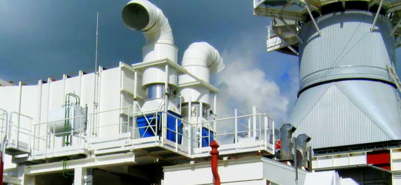
Gas turbine enclosure ventilation
During these last 30 years, SAI has equipped over 600 power plants worldwide with complete ventilation system with airflow that are often exceeding 1 000 000 m3/h.
Ventilation system are designed and manufactured by SAI to solve complex issues in order to:
- Respect acoustic objectives both outdoor but also sometimes indoor
- Efficiently remove heat generated inside of the building & enclosures
- Cool specifically sensitive components
- Ensure the right air change to meet the ATEX requirement
- Avoid gas pockets inside of the engine halls or turbine enclosures
- Prevent from airborne pollution thanks to various kind of filtration technologies
- Heat or cool the ambient air to blow the right temperature depending on the site conditions
Calories and gas pockets dissipation
SAI enclosures can be equipped with ventilation systems allowing the dissipation of calories according to our CFD calculations. For safety reasons, it is also necessary to evacuate gas pockets which can be formed by a leak. According to input data, site conditions and CFD results, an enclosure ventilation system can be configured differently:
Forced or natural ventilation
Ventilation is forced when the system integrates a motor-fan in order to achieve air movement objectives. On the other hand, a natural ventilation includes openings which dimension and position are specifically calculated to ensure sufficient airflow.
Pressurized or depressurized ventilation
When forced, ventilation systems can be at pressure or vacuum conditions depending on motor-fan airflow direction compared to the enclosure.
Filtered or unfiltered ventilation
For complex site conditions (salt, dust, sand…), ventilations can incorporate a filtration system inside air inlets.
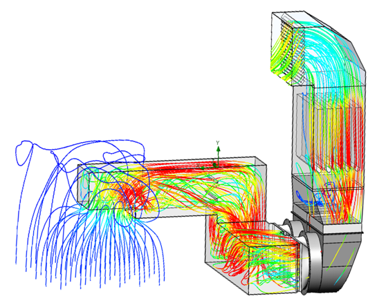
A design based on our CFD calculations
Computational fluid dynamics is used to quantitatively predict fluid physical phenomena of ventilation. Through input data analysis (flow rate, pressure drop…) and CFD simulation, SAI experts are able to custom size your ventilation system taking into account air velocity and the different components of your ventilation system. Proper moto-fan dimensioning and selection of rotation speed, material, power, etc., is a key step in the energy consumption reduction of a ventilation system. When the installation operating flow rate is known, it is necessary to compare fan efficiency curves in order to select the most appropriate model for your installation. SAI team of engineers have years of experience in pushing the limits of current ventilation strategies in order to produces environmentally responsible designs
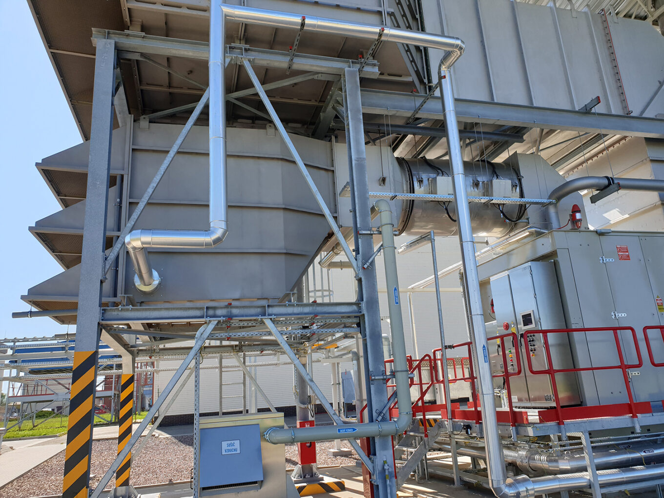
Composition of forced ventilation system
- Baffle-type or circular / tubular silencers
- Non-return valves
- Sand filters, weather louvers, bird screen, snow hoods…
- Motorized rectangular or circular dampers
- Various duct arrangement: circular, rectangular…
- Motor fans
Various options available
- Hazardous & classified areas (ATEX, UL…)
- Heating systems
- 50 Hz or 60 Hz motors
- Stainless steel construction
- Gas detectors, pressure drop transmitters…
- Complete electrical packages
- Filtered ventilation (G2, G3, G4 up to F9)
- Corrosiveness categories up to C5VH